You can create a wide variety of shapes to highlight and/or illustrate aspects of your document.
You can place a shape in your document by any of the following methods (in this context, a “text box” is a shape).
Nisus Writer Pro supports three kinds of shapes. These are illustrated in the various Shapes menus themselves, as is seen in Figure 211 on page 226. They are:
• Text and Callout Boxes
• Lines and Arrows
• Geometrical forms and Brackets
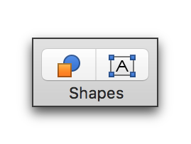
Figure 208
The Text Box and Shape buttons on the Toolbar
☞ Nisus Writer Pro also lets you insert a “Canvas”, a fourth kind of shape, which enables you to work on a number of shapes together.
You can insert a shape in your document by any of the following methods:
► choose any of the shapes or text boxes available from the menu Tools > Insert Shape
► choose any shape available from the Shapes buttons on the Toolbar as illustrated in Figure 208.
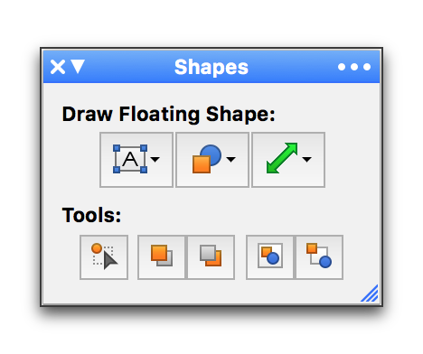
► choose any shape available from the three Draw Floating Shape buttons at the top of the Shapes palette as illustrated in Figure 209. The Tools buttons are explained in detail in the section “Modify shapes” beginning on page 237.
☞ If you are in any view other than Page View when you insert a shape, Nisus Writer Pro automatically switches to Page View. Floating images only appear when in Page View and only in the main portion of your document’s text: not in footnotes, endnotes, headers, footers, nor comments.
While there are default appearances for shapes (stored by shape type: Text or Callout Box, Lines, geometric type shapes), you can change them using the available menus. If you select an existing shape before drawing a new one, the new shape will use the selected existing shape as a template.
As you work with shapes, keep these guidelines in mind:
• When you insert a shape you enter a special mode and cannot enter text in the normal text area of your document
• a banner appears across the top of your document instructing you to “Click and drag to draw the new shape.”
• a banner appears across the bottom of your document instructing you to “Press the escape key (ESC) to cancel.”
☞ Undoing and redoing are disabled.
• Once you draw the new shape it is selected in your document and ready for you to manipulate.
Use text and callout boxes to add free-floating blocks of text to your document.
Almost anything you can do in normal Nisus Writer Pro text you can do in a Text or Callout Box.
• type, copy, paste and drag & drop text
• undo and redo
• modify any character based formatting
• modify ruler and other paragraph formatting
• apply any styles associated with the document
• use the list tools of Nisus Writer Pro
• use the table tools of Nisus Writer Pro
• check your spelling
• use the Nisus Writer Pro QuickFix features
• add hyperlinks, bookmarks and cross-references and other automatically updating content
☞ If you bookmark text in a Text or Callout Box and add a cross-reference to that elsewhere, location-type cross-references will not display correctly.
• paste inline images
• add comments
• track changes
There are a few things you cannot do.
• add footnotes/endnotes
• mark text for an index or table of contents
• nest Text or Callout Boxes
☞ Every Text and Callout Box has a Link button
◦ The Link button, the smaller red rectangle in Figure 210, is a small blue arrow that appears just outside and to the right of the box. Its use is explained in step b on page 228.
◦ If the text inside the box is too large to fit inside the currently set size of the box, an Expand button appears in light gray in the lower left corner of the box as illustrated the larger red rectangle in Figure 210. Its use is explained in step 3 on page 227.
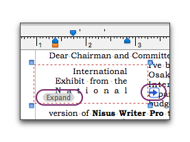
Figure 210
The ruler indents of a text box showing Expand button in the lower left and the Link button (the arrow) to its right
◦ Callout, Rounded Speech Box
from the menu Tools > Insert Shape or the Text Box button on the Toolbar, or the Text Box button in the Draw Floating Shape portion of the Shapes palette.
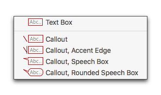
Figure 211
The Text Box menu as it appears from the Text Box button on the Shapes palette
The box appears ready for you to enter text as illustrated in Figure 212. Three of the five available styles of Text and Callout Boxes are illustrated in Figure 213.
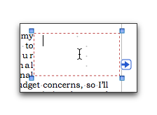
Figure 212
A Text Box ready for text
2. Type or paste the text you want into the Text or Callout Box.
When you create a Text or Callout Box, Nisus Writer Pro creates a new style for your document called Shape Text based on the paragraph and character formatting of the Normal style of your document. If you have already created a Shape Text style as part of your Nisus New File, Nisus Writer Pro uses the characteristics of that style. You can modify both the ruler and character formatting as illustrated in Figure 210 on page 226 and Figure 215 on page 229.

Figure 213
Text and Callout Boxes
► Click the Expand button to enlarge the Text or Callout Box.
or:
a. Create a new Text or Callout Box.
b. Click the Link button in the first box.
Nisus Writer Pro displays a banner across the top of the document as illustrated in Figure 214: Click the destination text box where text should flow. In addition a banner across the bottom of the document appears that states: Press the escape key (ESC) to cancel.
☞ Undoing and redoing are disabled.
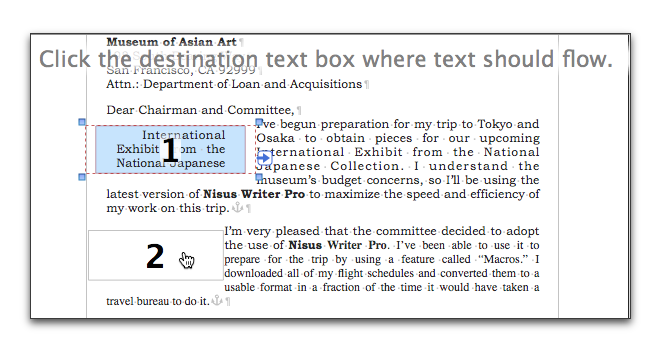
Figure 214
Creating a linked Text Box
c. Click the Text or Callout Box to which you want the text to flow as illustrated in Figure 214.
You can have text flow from one to a second and third or more Text or Callout Boxes. If you have more than one available Text or Callout Box you can choose from any available box.
☞ If the Text or Callout Box to which you are linking already has some text in it, the overflow of the linked Text or Callout Box appears ahead of whatever text was there.
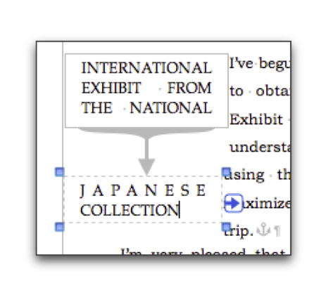
Figure 215
Linked text boxes with altered ruler and font
When you link the Text or Callout Boxes a “flow arrow” appears from the first Text or Callout Box to each succeeding box containing linked text when any of text boxes are selected as illustrated in Figure 215. The arrows appear in the color set for the Invisibles that display when you choose the menu command: View > Show Invisibles. You can set this color in the Appearance preferences as explained on page 589.
Use Text Boxes to write vertical East Asian text
East Asian languages: Chinese (Simplified or Traditional), Japanese, and Korean Hangul, can be written horizontally or vertically. You can use vertical text boxes in Nisus Writer Pro to add a different orientation within the horizontal orientation of Nisus Writer Pro’s default page layout. The vertical text boxes are not a solution for full-page vertical text layout, but rather an extra feature to embellish your default horizontal text layout.
Terminology for the different orientation in the different writing systems are:
• horizontal
◦ Chinese (Simplified) hengpai 横排; (Traditional) 橫排;
◦ Japanese yokogaki 横書き; yokogumi 横組み;
◦ Korean garosseugi 가로쓰기; hoengseo 횡서; 橫書;
• vertical
◦ Chinese (Simplified) zongpai 纵排 (Traditional) 縱排;
◦ Japanese tategaki 縦書き; tategumi 縦組み;
◦ Korean serosseugi 세로쓰기; jongseo 종서.
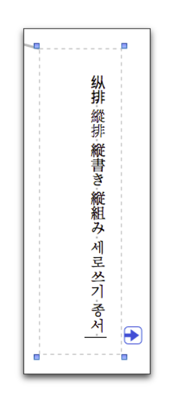
Figure 216
Some vertical text representing the terms for East Asian horizontal and vertical text showing the insertion point at the bottom
You can input (type/paste), these Asian scripts inside a standard Nisus Writer Pro text box.
1. Choose the menu command: Tools > Insert Shape > Text Box.
2. Draw the text box to the size of the area you want your text to appear in.
You can use the entire document.
3. Make sure the insertion point is in the upper left corner of the text box.
4. Choose the menu command: Format > Paragraph > Align Justified.
5. Enter your text (type or paste).
6. When finished choose the menu command: Format >Vertical Layout Orientation.
The command Vertical Layout Orientation toggles on and off.
Alternatively, you may choose to input text vertically in real time rather than horizontally
1. Choose the menu command: Tools > Insert Shape > Text Box.
2. Draw the text box to the size of the area you want your text.
3. Make sure the insertion point is in the upper left corner of the text box.
4. Choose the menu command: Format > Paragraph > Align Justified.
5. Choose the menu command: Format > Vertical Layout Orientation.
6. Enter your text.
This rotates the insertion point 90º and moves it to the top right text box ready for you to enter your text.
☞ By using floating text boxes to layout vertical text, you can have both horizontal and vertical text mixed on a single page. The main document body can have a horizontal orientation wrapped around an inserted floating text box with a vertical layout orientation.
☞ Table cells in a table can also use vertical text layout mode.
Use Text Boxes to create a “Drop Cap”
While Nisus Writer Pro does not currently support an automatic drop cap capability, you can accomplish this using the “Images”.
1. Choose the menu command: Tools > Insert Shape > Text Box.
2. Drag the “Cross Hair” pointer to the approximate size you want the dropped cap.
3. Type the character you want for the dropped cap.
4. Select the character and set its formatting using the tools of the Character palette.
5. Resize the text box so that it “hugs” the character.
6. Select the text wrap option from the menu: Tools > Shapes > Wrap Text Around Shape.
7. Drag the character to the beginning of the paragraph where you want it.
8. Adjust the padding as needed using the Padding section of the Shape Wrap palette.
You can make other modifications as needed.
An example of this drop cap is illustrated in the following paragraph
W
hile Nisus Writer Pro does not currently support an automatic drop cap capability, you can accomplish this using the “Images” tools. Choose the menu command: Tools > Insert Shape > Text Box. Drag the “Cross Hair” pointer to the approximate size you want the dropped cap. Type the character you want for the dropped cap. Select the character and set its font/size/options using the tools of the Character palette. Resize the text box so that it “hugs” the character. Select the text wrap option (from the menu): Tools > Shapes > Wrap Text Around Shape. Drag the character to the beginning of the paragraph where you want it. Adjust the padding as needed using the Padding section of the Shape Wrap palette. That should do the trick. You can make other modifications as needed.
Figure 217
A paragraph with a dropped cap
Link multiple text or callout boxes
You may have a number of Text or Callout Boxes in your document and want to change the way the text flows from one to another.
1. Choose the menu command: Tools > Shapes > Enter Text Box Linking Mode.
A message displays: Click the source text box.
When you hover your pointer over one of the text boxes it is identified as the source by displaying a 1.
☞ If you click outside of any text box, Nisus Writer Pro returns to normal text editing mode.
2. Choose your box.
Message displays: Click the destination text box where text should flow.
When you hover your pointer over any of the remaining text boxes they are each identified as the destination by displaying a 2.
3. Choose your box.
The flow arrow illustrated in Figure 215 appears, connecting the two boxes and the overflow text hidden in the first box appears in the second. The first box and all its text is highlighted. Text Box Linking Mode is ended.
☞ If there is more text still hidden, you need to enter text box linking mode once again and repeat the procedure.
When you do repeat the process, what had been box 1 is no longer available to choose and what had been box 2 is now box 1.
Using floating, linked Text or Callout Boxes you can create very complex documents as illustrated in Figure 218.
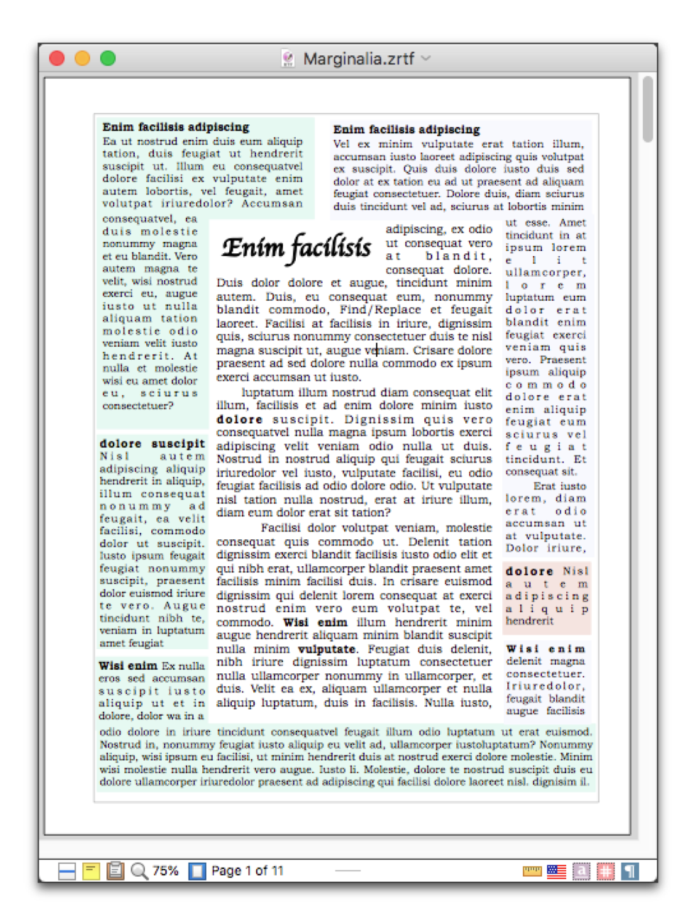
Figure 218
Using linked Text Boxes to create a document with a form of marginalia
Nisus Writer Pro has always had the ability to add automatically incrementing numbered captions to figures consisting of inline images. This procedure is explained in “Use list styles to automatically number figures, tables, etc.” on page 66. You can add captions to floating images as well.
1. Select an inline image to which you want to add a caption.
2. Choose the menu command: Tools > Shapes > Add Caption to Image.
☞ Adding a caption in this manner to an inline image causes it to float.
The image is placed, centered, at the top of a Text Box with the text: “Image Caption” beneath it, selected, ready for you to add your description as illustrated in Figure 219.
3. Type the description of your image.
The text box expands, horizontally, as needed.
☞ Anything you can do with other text boxes, explained in “About Text and Callout Boxes” on page 225, you can also do with a caption text box.
☞ While you cannot add a caption to a floating shape, you can convert it to an inline image and then add a caption to that, causing it to float once again.
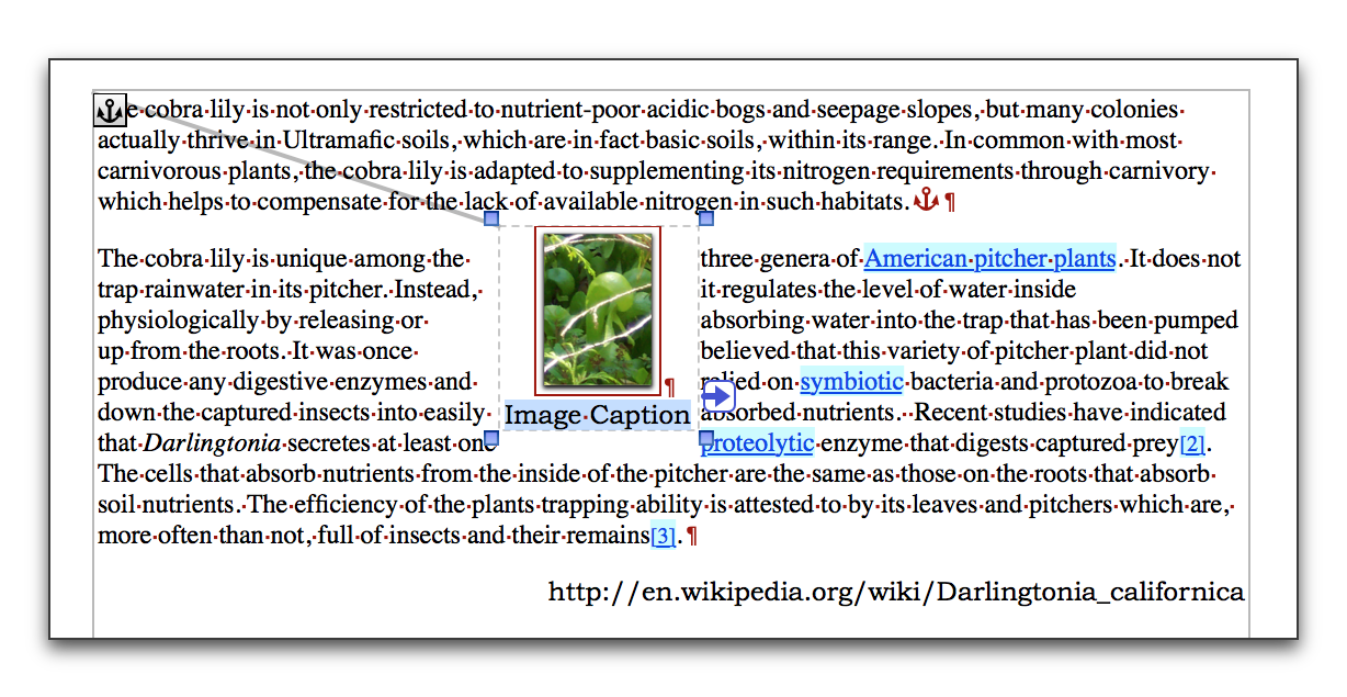
Figure 219
The inline image of Figure 179 on page 197 with a caption added
You can draw a variety of lines and/or arrows in your document.
1. Choose any one of the arrows available from the arrows and lines portion of the menu Tools > Insert Shape illustrated in Figure 220.

Figure 220
The Lines menu as it appears from the Lines button on the Shapes palette
2. Click and drag where you want the line or arrow to appear.
a. Press ⇧ as you draw to constrain the line or arrow to a 45º angle.
b. For a single-headed arrow, draw from any location to where you want the arrow to point.
In the Shape Stroke palette illustrated in Figure 221 you can determine:
• the kind of line from the pop-up menu at the left. These lines are the same lines illustrated in Figure 268 on page 290,
• the line’s thickness from the pop-up menu on the right.
• the line’s color by clicking the Color swatch to open the Colors panel,
• the line’s Opacity, by entering a specific percentage or dragging the slider to the amount desired.
• the shape of the end-point of the line.
The squares surrounding the line at the bottom of the palette indicate two pop-up menus that offer a variety of “arrowheads” from which you can choose for either end. This is illustrated in Figure 222 which has a point on the upper end and a ball on the lower.
☞ Some line strokes cannot be used with certain shapes. For example multiple line strokes cannot be used around circles though dashed strokes can.
.png)
Figure 221
The Shape Stroke palette
Make a line into an arrow, or an arrow into a line
You can transform any line into a single or double-headed arrow (or the reverse).
► Choose from the various arrowheads available at the bottom of the Shape Stroke palette.
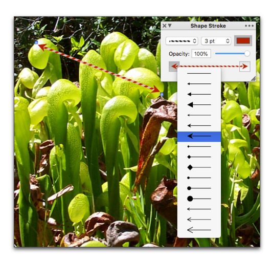
Figure 222
Creating a colorful double-headed arrow using the Shape Stroke palette
☞ A couple of issues to be aware of:
• Arrows and Lines do not have fill.
• Arrows and Lines do not curve.
• You can use the Rotate tools of the Shape Metrics palette as well as the menu commands Tools > Shape Metrics > Rotate Counterclockwise or Rotate Clockwise to aim your arrows in any direction.
• All of the controls of the Shape Stroke palette are also available (with limited options) on the Shape Stroke submenus of the Tools menu. These are listed on page 701.
☞ One of the values of having all these commands on the menus as well as the palette is that you can assign keyboard shortcuts to them as explained in “Menu Keys for Menu Commands” on page 578, as well as use the commands in automating tasks using macros as explained in “Macros, an Introduction” on page 629.
While the block arrows are, indeed, arrows, they function more as the other geometrical shapes than they do as lines and line arrows. You can learn more about these features in the following section “Geometric type shapes”.
Nisus Writer Pro can create a variety of geometrical and quasi geometrical shapes in your document.
Enter a shape in your document
You create a shape in your document using essentially the same method as explained for entering a Text or Callout Box or a line or arrow.
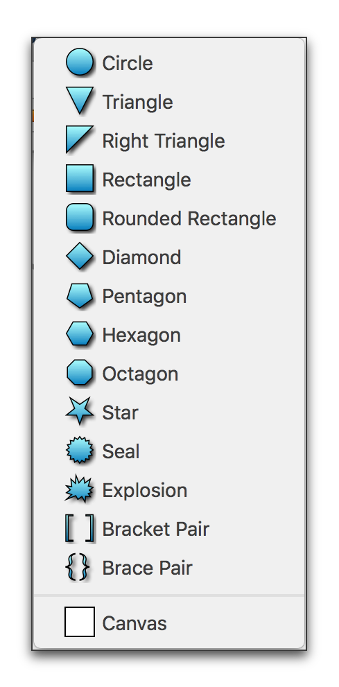
Figure 223
The Shapes menu as it appears from the Shapes button on the Shapes palette
1. Choose whatever shape you want from the menu Tools > Insert Shape illustrated in Figure 211 on page 226.
◦ a banner appears across the top of your document instructing you to “Click and drag to draw the new shape.”
◦ a banner appears across the bottom of your document instructing you to “Press the escape key (ESC) to cancel.”
☞ Undoing and redoing are disabled.
2. Click and drag to create the shape wherever you want on the page.
☞ When you draw a new shape, press ⇧ to create a uniform shape with a 1:1 aspect ratio (for example a perfect circle or square or an equilateral triangle).
3. Resize the shape using the four handles and or the four perimeter lines as needed.
The pointer changes to a resizer  when over the handles and the margin mover
  or
or  when over the perimeter lines. As you change the shape’s size the four resize handles are hidden.
☞ If you resize the shape, pressing ⇧ maintains the shape’s current proportions.
☞ If you change the proportions and want to restore them right-click the shape and choose Restore Original Proportions from the context menu that appears.
4. Move the shape wherever you want on the text portion of your document.
The pointer changes to the grabbing hand  when it is over the interior of the shape.
☞ When you create a shape, its initial Placement is set to Floats on Page of ¶ and it is set for the text of the document to wrap around it as illustrated in Figure 232 which shows a Canvas.
Once you have created a shape in your document, there are a wide variety of things you can do with it. When you select a shape the drawing tools palette group becomes active (if you have the Palette Dock open and have not changed the preferences).
The drawing tools palette group has all the controls available for manipulating shapes in Nisus Writer Pro. It consists of five palettes:
• Shapes, explained in “Use the Shapes palette” beginning on page 224 and “More tools on the Shapes palette” below
• Shape Wrap, explained on page 197 and in detail in the section “Use the Shape Wrap palette” beginning on page 209
• Shape Stroke, explained on page 234
• Shape Fill explained on page 242
• Shape Shadow explained on page 243
• Shape Metrics explained on page 244
Each of these has commands that match commands on the Tools menu. However, because some controls are unique to the palettes the following instructions will refer to them, with some reference to the commands if their names differ and when additional commands are available on the menus.
More tools on the Shapes palette
The Shapes palette, illustrated in Figure 209 on page 224 has three pop-up menu buttons that enable you to draw shapes such as Text or Callout Boxes, geometric type shapes and arrows. The five buttons in the Tools section of the palette enable you to manipulate those objects.
|
Shapes palette Tools buttons |
||||
|
|
|
|
|
|
|
Enter\Exit shape selection mode. |
Bring selected floating shapes to the front. |
Send selected floating shapes to the back. |
Group together selected floating shapes. |
Ungroup selected floating shapes. |
Table 7
The Tools buttons on the Shapes palette
From left to right:
• Enter floating shape selection mode.
This is the same as choosing the menu command: Tools > Shapes > Enter Shape Selection Mode.
Similar to when you insert a shape or a Text or Callout Box, Nisus Writer Pro enters a mode in which:
• a banner appears across the top of your document instructing you to “Click and drag to select shapes.”
• a banner appears across the bottom of your document instructing you to “Press the escape key (ESC) to cancel.”
You can also click the same button to exit the mode.
• Bring selected floating shapes to the front.
This is the same as choosing the menu command: Tools > Shapes > Bring to Front.
If you have two or more shapes in your document (or in a Canvas), it brings the selected object(s) in front of all the others, regardless of their previous sequence, though it maintains the sequence of the objects selected.
For example, if you have 7 objects and select three which happen to be (in sequence) #3, 4, & 6. When you bring them to the front, they will now be objects 1, 2, 3 followed by objects 1, 2, 5 & 7.
• Send selected floating shapes to the back.
This is the same as choosing the menu command: Tools > Shapes > Send to Back.
If you have two or more shapes in your document (or in a Canvas), it sends the selected object(s) behind all the others, regardless of their previous sequence, though it maintains the sequence of the objects selected.
For example, if you have 7 objects and select three which happen to be (in sequence) #3, 4, & 6. When you send them to the back, they will now be objects 5, 6 and 7 after objects 1, 2, 5 & 7.
• Group together selected floating shapes.
This is the same as choosing the menu command: Tools > Shapes > Group Shapes.
If you select two or more shapes in your document, it groups the selected objects so that they move as one unit.
• Ungroup selected floating shapes.
This is the same as choosing the menu command: Tools > Shapes > Ungroup Shapes.
If you have grouped two or more shapes in your document, it causes those grouped shapes to revert to their ungrouped state so they can be manipulated individually.
Select floating shapes without selecting text
The sequence of which shape is selected can seem complex. Keep these rules in mind.
When you create your shapes, each new object you create is placed “in front of” the preceding ones. Their sequence, however, for the purpose of selection by the commands Select Next Shape or Select Previous Shape is determined not by the order in which they were created or last manipulated, nor is the sequence determined by which appears to be laying on top of another. The sequence is based on which shapes are anchored closest to the top of the document, followed by which are its position in that paragraph.
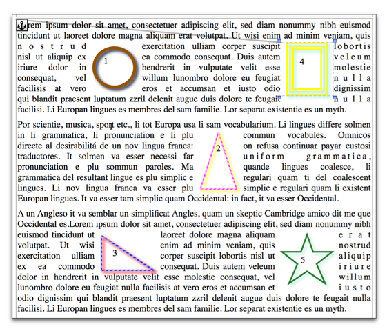
Figure 224
Sequence of shapes in multiple paragraphs each shape anchored to the paragraph in which it appears
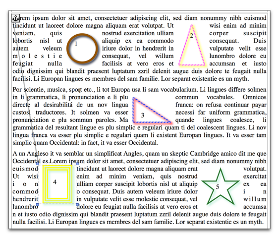
Figure 225
Sequence of shapes in multiple paragraphs each shape anchored to the paragraph in which it appears in Figure 224
► Click the Enter floating shape selection mode button from the Tools section of the Shapes palette.
► Choose the menu command: Tools > Shapes > Enter Shape Selection Mode.
► Choose the menu command: Tools > Shapes > Select Next Shape to select the closest shape following the location of your insertion point.
► Choose the menu command: Tools > Shapes > Select Previous Shape to select the closest shape above the location of your insertion point.
• All shapes anchored to “paragraph one” come before those anchored to “paragraph two,” regardless of the shapes’ visible position to one another.
• With those shapes that are all anchored to the same paragraph, the highest shape, in its vertical distance from the top of the page, is first.
This is illustrated in Figure 226 and the explanation following it.
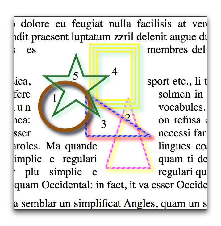
Figure 226
The sequence of shapes in one paragraph
◦ Green Star #5 is “in front” of
◦ Brown Circle #1 which is in front of
◦ Purple & Pink Right Angle Triangle #3 which is in front of
◦ Triple Yellow & Green Rectangle #4 which is in front of
◦ Pink & Red Isosceles Triangle #2.
However, the shape closest to the top of the document is the Triple Yellow & Green Rectangle #4. So, if your insertion point is in the word “feugiat” or above in Figure 226 when you choose Select Next Shape, the first shape selected is #4, then #5, #1, #3, and finally #2.
Conversely, if your insertion point is in the word “Occidental” or below in Figure 226 and you choose Select Previous Shape the sequence of shapes selected is #2 then #3, #1, #5, and finally #4.
☞ If you alter the vertical offset, the sequence of “highest” changes, and thereby the sequence of which is selected using the commands Select Next Shape and Select Previous Shape is changed.
Rearrange the front to back order of various floating shapes
The sequence of floating shapes is determined by their distance from the top of the document. However, as illustrated in Figure 226, different shapes can be set one atop another so that they can appear to be layered. You can change the which one lays atop another.
Bring selected shape(s) to the front
1. Choose one or more shapes.
2. Choose the menu command: Tools > Shapes > Bring to Front.
If you have multiple shapes selected and bring them to the front their relative stacking order is maintained.
Send selected shape(s) to the back
1. Choose one or more shapes.
2. Choose the menu command: Tools > Shapes > Send to Back.
If you have multiple shapes selected and send them to the back their relative stacking order is maintained.
Cause selected objects to function as a single unit
1. Select two or more shapes and/or images.
2. Choose the menu command: Tools > Shapes > Group Shapes or click the Group button in the Tools portion of the Shapes palette.
This groups the selected objects to be affected as if they move as a unit.
A group is like any other shape. It has its own border, fill, etc. Changing the metrics of grouped shapes do not directly affect all the shapes in the group. Rather, the metrics of the group are changed, which means all shapes inside the group are along for the ride; a group scales the shapes inside it.
Grouping shapes, creates a new bounding box that surrounds the grouped graphics. When you select a set of shapes that have been grouped, any changes made in the
◦ Shape Wrap palette causes the text wrap options to wrap around the bounding box, not the individual shapes. When you choose to have text wrap around the actual shape of the image, the text wraps around what would be the bounding box of the ungrouped shapes.
◦ Shape Stroke palette affect the group’s bounding box and not the individual shapes.
◦ Shape Shadow palette affect the group’s bounding box and not the individual shapes.
◦ Shape Metrics palette affect all the shapes in the group proportionately.
◦ Shape Fill palette affect the groups bounding box and not the individual shapes that do not already have a fill.
☞ You can also work on multiple floating shapes that are selected, but not grouped. In this case whenever you change a characteristic using any of the palettes, all selected objects are affected.
Cause grouped objects to function as a individual items
1. Select grouped shapes and/or images.
2. Choose the menu command: Tools > Shapes > Ungroup Shapes or click the Ungroup button in the Tools portion of the Shapes palette.
This ungroups the selected objects so they can be dealt with individually.
☞ If you have a group selected, click again on a shape inside that group. This selects a shape inside that group with a single shape selected (that can be individually manipulated).
Work with multiple selected shapes
You can also work on multiple floating shapes that are selected, but not grouped. In this case whenever you change a characteristic using any of the palettes, all selected objects are affected.
Every shape can have its own fill using the Shape Fill palette illustrated in Figure 227. This fill functions much the same way as table cell shading, explained in “Set the shading (color) of cells” on page 292, with the additional ability to change the opacity of the shape.
This pop-up menu corresponds to the commands found on the Style submenu of Shape Fill sub-menu of the Tools menu. The default colors available are listed on page 700.
☞ One of the values of having all these commands on the menus as well as the palette is that you can assign keyboard shortcuts to them as explained in “Menu Keys for Menu Commands” on page 578, as well as use the commands in automating tasks using macros as explained in “Macros, an Introduction” on page 629.
1. Select the shape(s) you want to change.
2. Drag the Opacity slider in the Shape Shadow palette or enter the percentage of opacity you want.
As an alternative, you can choose commands from the menu Tools > Shape Fill > Opacity to set the opacity of the fill of selected shapes. The available options appear in 10% increments from 0% (Clear) to 100% (Solid).
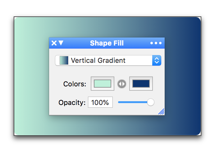
Figure 227
The Shape Fill palette using a Vertical Gradient and the colors represented
Every shape can have a shadow, as illustrated in Figure 226 on page 240 using the Shape Shadow palette illustrated in Figure 228.
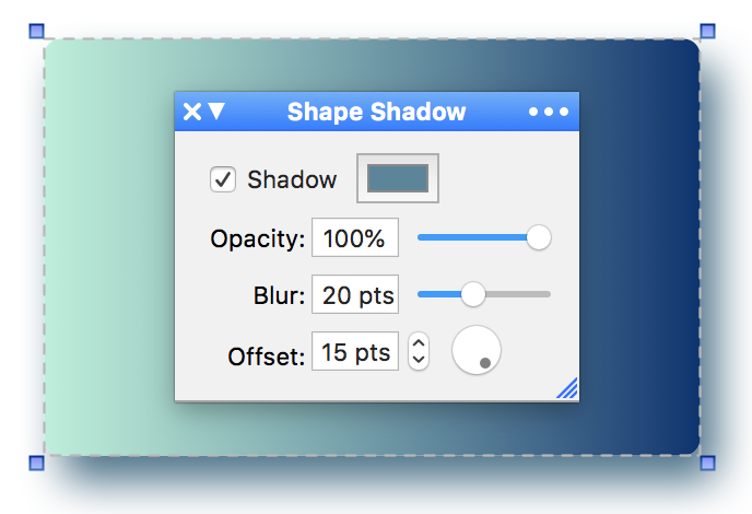
Figure 228
The Shape Shadow palette and the shadow it creates based on the shape of Figure 228
1. Select the shape(s) you want to have a shadow.
2. Check (turn on) Shadow in the Shape Shadow palette.
3. Click the color swatch to open the Colors panel if you want a shadow in a color other than black.
4. Drag the Opacity slider in the Shape Shadow palette or enter the percentage of opacity you want.
The less opaque (the lower the percentage), the less visible the shadow.
5. Drag the Blur slider in the Shape Shadow palette or enter the amount of blur (in points) you want.
The slider only goes up to 50 pts, but you can enter higher numbers using the keyboard. The higher the number, less visible the shadow.
6. Determine the Offset by using the stepper or entering a value using the keyboard.
The higher the number the further the shadow is from the shape.
☞ Press ⌘ when you click a palette stepper’s up or down arrow to apply the shown value uniformly to all selected text, instead of adjusting all selected values independently.
7. Set the “light source” by turning the dial.
The little circle in the dial indicates the point opposite the light source.
As an alternative, you can choose commands from the menu Tools > Shape Fill > Shadow to set the shadow of selected shapes. The available options are limited to None, Glow, Normal and Hard.
☞ If you give your group a solid fill or stroke, you can give it a shadow too.
You can determine the precise size and location of your shapes using the Shape Metrics palette illustrated in Figure 229.
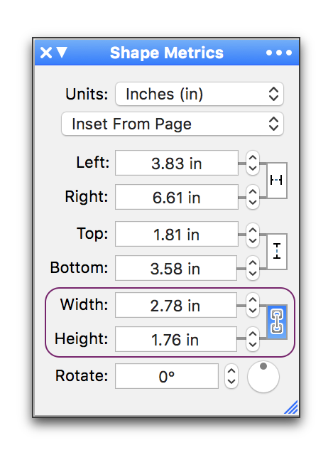
Figure 229
The Shape Metrics palette with the Width and Height dimensions linked and highlighted
|
Shapes Metrics palette link buttons |
|||||
|
Width Link button |
Height Link button |
Aspect Ratio Link button |
|||
|
Off |
On |
Off |
On |
Off |
On |
|
|
|
|
|
|
|
Table 8
The Shape Metrics palette link buttons
1. Select the shape(s) you want to change.
2. Choose the measuring units you want to use from the Units pop-up menu in the Shape Metrics palette.
You can display the units either as they are preset on the ruler (Ruler Units), or any of the other units supported: Centimeters (cm), Inches (in), Millimeters (mm), Picas (pc) or Points (pt).
3. Determine whether the horizontal and vertical alignment should be measured
◦ from the edge of the paper: choose Inset From Page
◦ or from the paragraph to which it is anchored: choose Inset from Paragraph.
Move selected shapes by precise, designated amounts
1. Select the shape(s) you want to change.
2. Use the steppers or enter a value using the keyboard to move the selected shape(s) to the Left, Right, towards the Top, or Bottom.
☞ Press ⌘ when you click a palette stepper’s up or down arrow to apply the shown value uniformly to all selected text, instead of adjusting all selected values independently.
a. Click (turn off) to un-link the Left and Right and/or the Top and Bottom controls so that moving one side does not move the other. This enables the shape to change its size.
b. Click (turn on) to link the Left and Right and/or the Top and Bottom controls so that moving one side also moves the other. This maintains the shape’s size, but changes its location.
These buttons correspond to the commands Shift Left, Shift Right, Shift Up and Shift Down found on the Shape Metrics sub-menu of the Tools menu.
☞ You can move a floating image so that it prints beyond the margins, but within the printer limits, as illustrated in Figure 230 below.
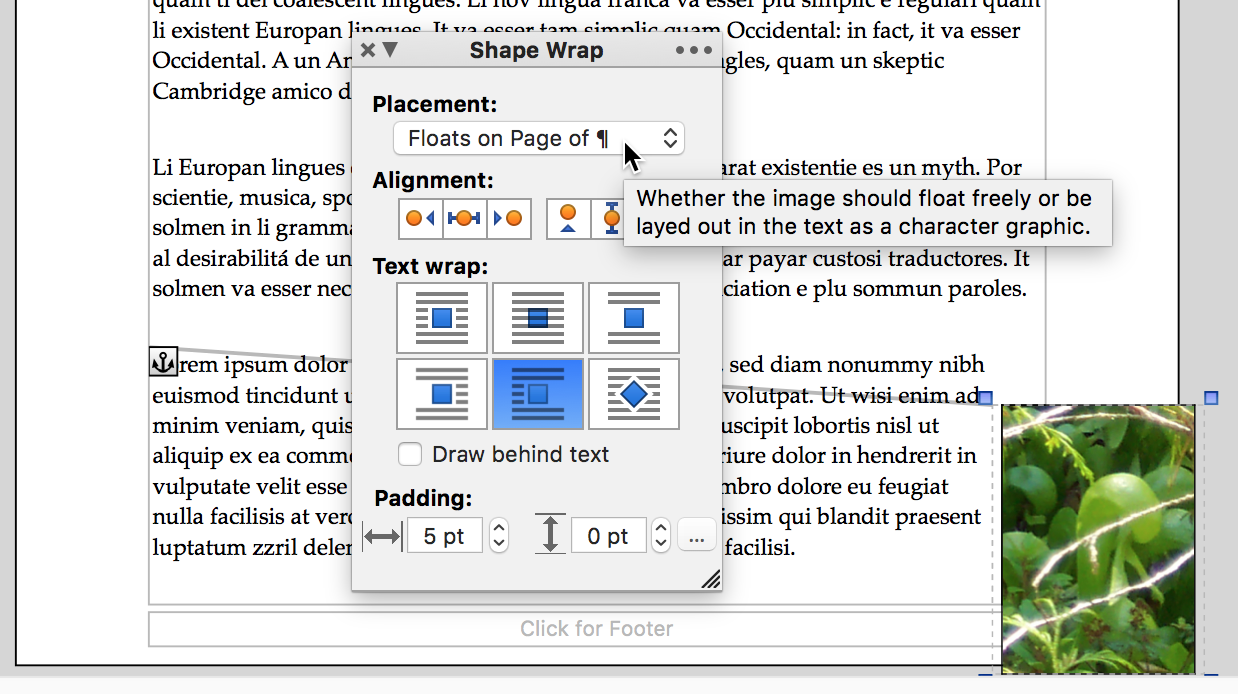
Figure 230
A selected floating image beyond the margin
Resize selected shapes by precise, designated amounts
1. Select the shape(s) you want to change.
2. Use the steppers or enter a value using the keyboard to alter the Width and/or Height of the selected shape(s).
☞ Press ⌘ when you click a palette stepper’s up or down arrow to apply the shown value uniformly to all selected text, instead of adjusting all selected values independently.
a. Click (turn off) to un-link the Width and Height controls so that changing the value for one does not alter the other. This enables the shape to change its proportion (from the upper left corner).
These buttons correspond to the commands Increase Width and Decrease Width as well as Increase Height and Decrease Height found on the Shape Metrics sub-menu of the Tools menu.
b. Click (turn on) to link the Width and Height controls so that changing the value for one changes the other. This maintains the shape’s aspect ratio as it grows or shrinks from its upper left corner.
These buttons correspond to the commands Increase Size and Decrease Size found on the Shape Metrics sub-menu of the Tools menu.
1. Select the shape(s) you want to change.
► turning the dial
► clicking the steppers or
► entering a value using the keyboard.
► Choosing the commands Rotate Clockwise and Rotate Counterclockwise found on the Shape Metrics sub-menu of the Tools menu.
Determine the values by which floating shapes and inline images adjust
The Shape Metrics palette offers precise, step by step, control of the values used to modify your shapes. The menu commands are preset to larger amounts. You can change these settings.
1. Choose Set Adjustment Amounts… from the Shape Metrics sub-menu of the Tools menu.
The Adjustment Settings dialog appears as illustrated in Figure 231.
2. Enter the values you want.
The options available are for:
◦ Shift Position By
◦ Resize By
◦ Change Height/Width By
◦ Rotate By
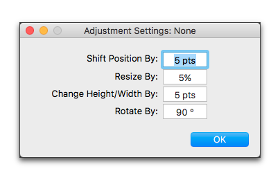
Figure 231
The Adjustment Settings dialog
Nisus Writer Pro also lets you insert a “Canvas”, which enables you to work on a number of shapes together, unencumbered by your text.
1. Choose the menu command: Tools > Insert Shape > Canvas.
◦ a banner appears across the top of your document instructing you to “Click and drag to draw the new shape.”
◦ a banner appears across the bottom of your document instructing you to “Press the escape key (ESC) to cancel.”
☞ Undoing and redoing are disabled.
2. Click and drag a rectangular Canvas wherever you want on the page.
3. Resize the Canvas using the four handles and or the four perimeter lines as needed.
The pointer changes to a cross hair  when over the handles and the margin mover
  or
or  when over the perimeter lines.
4. Move the Canvas wherever you want on the text portion of your document.
The pointer changes to the grabbing hand  when it is over the interior of the Canvas.
☞ When you create a Canvas, its Placement is set to Floats on page of ¶ and it is set for the text of the document to wrap around it as illustrated in Figure 232.
5. Click in the Canvas.
When you click inside a Canvas, Nisus Writer Pro disables everything but the Canvas and displays a flashing corner  where you click the pointer. This, illustrated in Figure 233, is the location where a pasted image’s upper left corner will appear.
You can choose to display the paste spot or not and determine its color, depending on how you set your options for “Invisibles & Guides” in the Appearance Preferences.
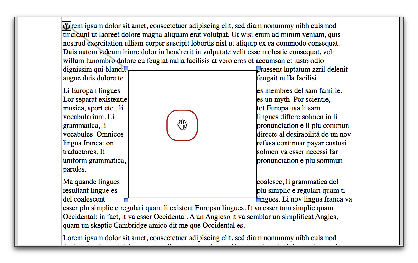
Figure 232
A Canvas ready for shapes
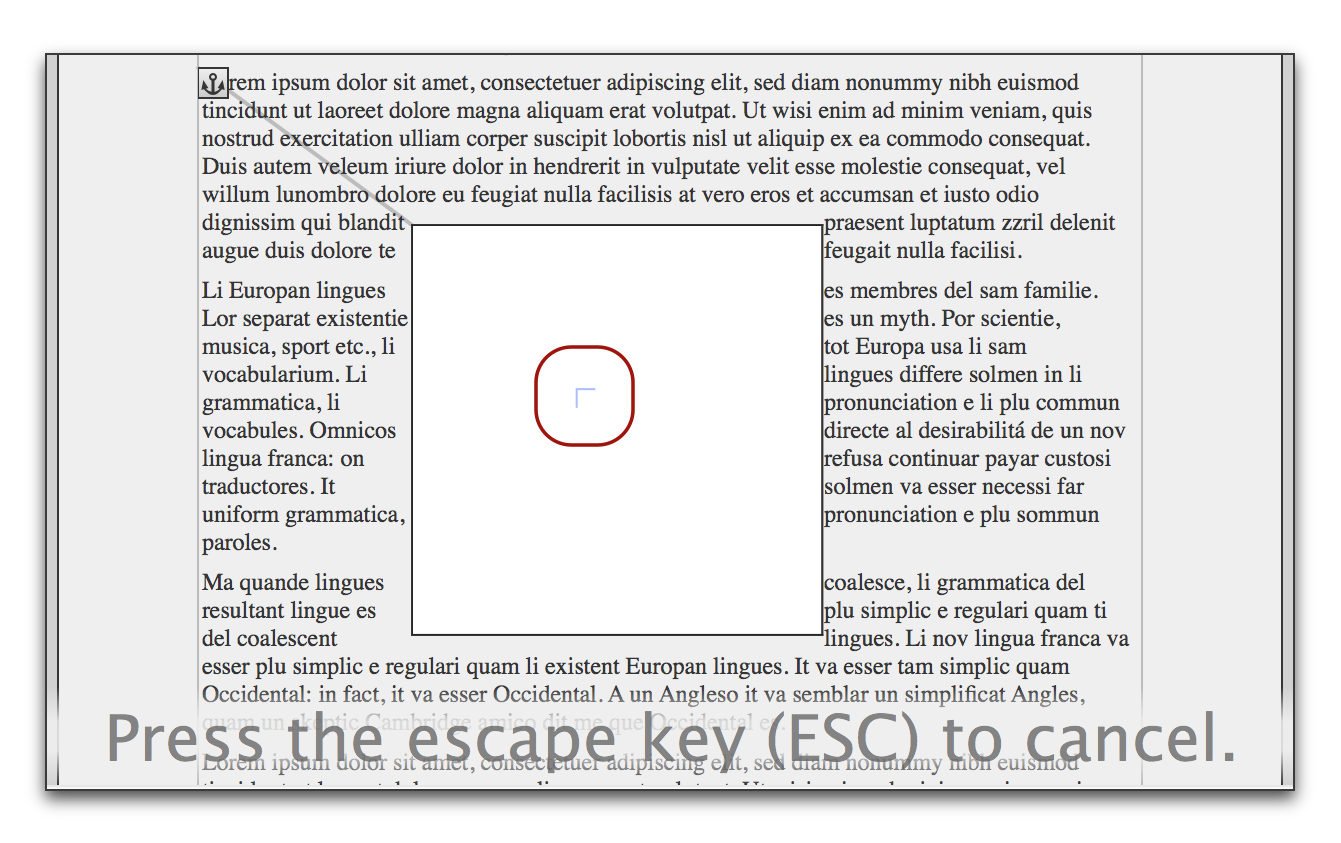
Figure 233
The Paste Spot inside the Canvas
6. Any shape you draw on top of a Canvas using various tools explained in this section will automatically be captured inside the Canvas.
☞ A Canvas can contain Text or Callout Boxes, lines and arrows, geometrical shapes and pasted images.
☞ You cannot group or ungroup objects inside a Canvas.
Additional tools for working with shapes
Set a preferred appearance for future drawn shapes
Nisus Writer Pro displays the appearance of the shape it will insert when you choose that from the various Insert Shape submenu or any of the other similar menus. The menus as illustrated in Figure 211 on page 226 (Text or Callout Boxes), Figure 220 on page 234 (Lines), and Figure 223 on page 236 (Shapes) indicate their appearance when you first start the application.
► Select a shape with the appearance you want for the next shape as illustrated in Figure 234 where the triangle (shape #2) is selected then the rectangle (shape #4).
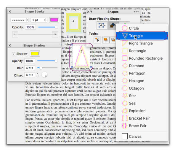
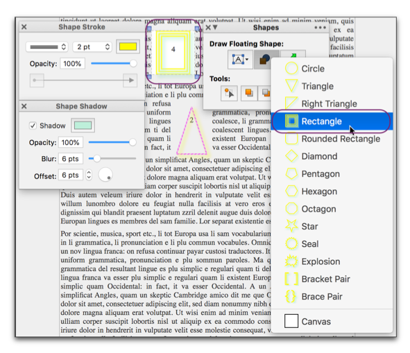
Figure 234
Selected shape determines appearance of inserted shape
You may decide that you want to use a particular shape’s appearance as the standard for a number of future shapes.
1. Select the shape with desired appearance.
2. Choose Use Selected Shape Appearance As Default from the Insert Shape or Shapes submenus of the Tools menu.
You can change this at any time using the same method.
Copy the appearance of one shape to apply to a different shape
If you have a shape in your document the appearance of which you want to apply to another shape, but you do not remember how your arrived at all of its settings, you can copy its appearance.
1. Select the shape the appearance of which you want.
2. Choose the menu command: Tools > Shapes > Copy Shape Appearance.
☞ You cannot copy the appearance of grouped shapes.
3. Select the shape(s) the appearance of which you want to change.
4. Choose the menu command: Tools > Shapes > Paste Shape Appearance.
You may need to have a number of identical copies of a particular shape.
1. Choose the menu command: Tools > Shapes > Duplicate Shape….
The Duplicate sheet appears as illustrated in Figure 235.
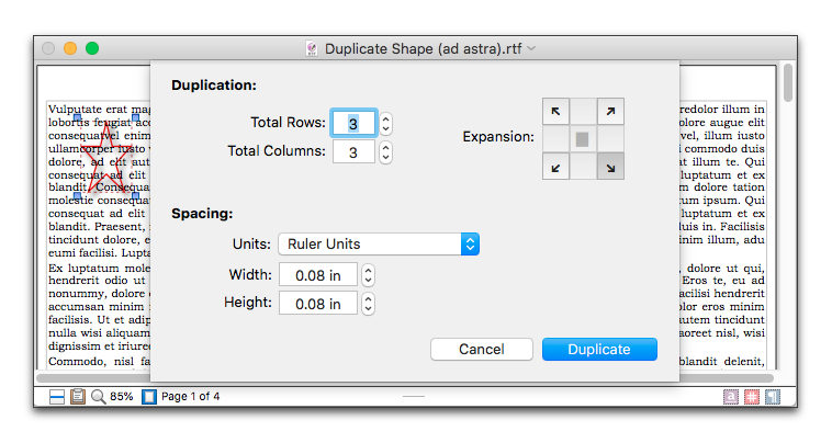
Figure 235
A shape ready to duplicate
2. Determine how many Total Rows and Total Columns you want from the Duplication portion of the sheet.
You can use the steppers or type or paste in the number you want.
☞ Press ⌘ when you click a palette stepper’s up or down arrow to apply the shown value uniformly to all selected text, instead of adjusting all selected values independently.
3. In the Expansion portion of the sheet, determine the direction: either to the lower right (the default), lower left, upper left, or upper right.
4. Set the Spacing between duplicates.
You can use the units either as they are preset on the ruler (Ruler Units), or any of the other units supported: Centimeters (cm), Inches (in), Millimeters (mm), Picas (pc) or Points (pt).
Set the Width and Height using the steppers or type or paste in the values you want
The result of the default settings is illustrated in Figure 236.
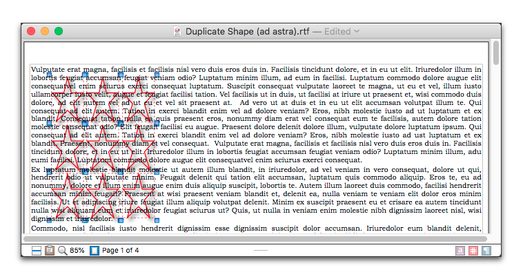
Figure 236
The shape of Figure 235 after a default duplication
| Previous Chapter Work with Floating Images |
<< index >> |
Next Chapter Book Tools |


